JTM Intelligent Equipment Co., Ltd.
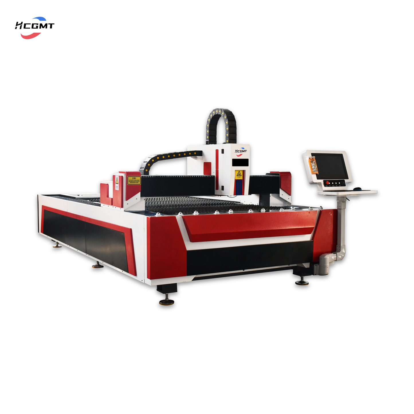
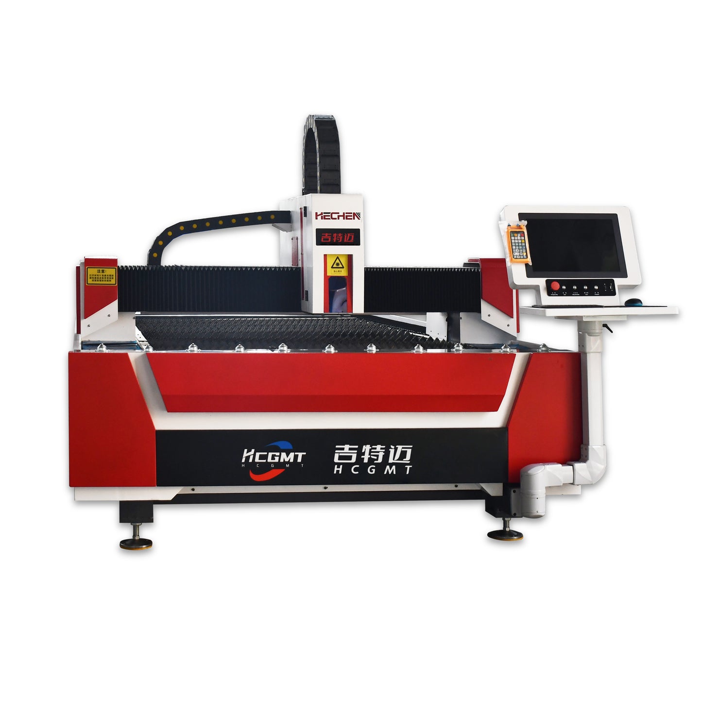
HCGMT® CNC Fiber Laser Cutting Machine
HCGMT® CNC Fiber Laser Cutting Machine
| HCGMT® Laser Cutting Machine Technical Parameters | |
| Laser Type | Fiber Laser |
| Laser Working Medium | Fibre Optics |
| Laser Line | 1060-1080M |
| Rated Output Power | 1500W/3000W/6000W/12000W |
| Beam Quality | <0.373Mrad |
| Axial Positioning Accuracy | 0.03MM/M≤+0.03MM/M |
| Maximum Cutting Range | 3*1.5M/4*1.5M/6*1.5M/4*2M/6*2M |
| Repositioning Accuracy | 0.03MM/M≤+0.03MM/M |
| Maximum Moving Speed | 120M/MIN |
| Power Rated Parameter | Three-phase AC 380V50HZ |
| Electrical Power | 17.3KW |
| Total Power Supply Protection Level | IP54 |
| Maximum Acceleration | 1.2G |
| Positioning Accuracy | ±0.05MM |
| Repositioning Accuracy | ±0.02MM |
| Working Voltage | 380V/50HZ |
| Cooling Type | Water Cooling |
| Note: All parameters are dynamic and for reference only. For more information, please contact customer service. | |
| Cutting Thickness & Speed Parameters | |||||||
| Material | Thickness(MM) | Gas | 1500W | 3000W | 6000W | 12000W | 15000W |
| Carbon Steel (Q235B) | Speed (M/MIN) | Speed (M/MIN) | Speed (M/MIN) | Speed (M/MIN) | Speed (M/MIN) | ||
| 1 | Nitrogen/Oxygen | 26-29 | 47-50 | 58-62 | |||
| 2 | Nitrogen/Oxygen | 7-8 | 21-23 | 31-36 | |||
| 3 | Nitrogen/Oxygen | / | 6-12 | 18-22 | 32-38 | 34-39 | |
| Oxygen | 2.9-3.2 | 3.9-4.1 | / | / | / | ||
| 4 | Nitrogen/Oxygen | / | / | 11-13 | 22-26 | 25-29 | |
| Oxygen | 2.4-2.6 | 3.4-3.6 | 3.7-4 | / | / | ||
| 5 | Nitrogen/Oxygen | / | / | 8-10 | 17-20 | 18-22 | |
| Oxygen | 1.8-2.0 | / | 3.2-3.3 | / | / | ||
| 6 | Air | / | / | 5.5-6.5 | 12-14 | 16-18 | |
| Nitrogen | / | / | 5.5-6.5 | 11-13 | 15-17 | ||
| Oxygen | 1.6-1.8 | 2.7-2.8 | 2.6-2.8 | 2.6-2.8 | 2.6-2.8 | ||
| 8 | Air | / | / | / | 8-10 | 10-11 | |
| Nitrogen | / | / | / | 7-9 | 9-10 | ||
| Oxygen | 1.1-1.3 | 2.1-2.3 | 2.5-2.6 | 2.5-2.6 | 2.5-2.6 | ||
| 10 | Air | / | / | / | 5-6 | 7-8 | |
| Nitrogen | / | / | / | 4.5-5.5 | 6.5-7 | ||
| Oxygen | 0.9-1.0 | 1.4-1.6 | 2.2-2.3 | 2.2-2.3 | 2.2-2.3 | ||
| 12 | Air | / | / | / | 4.2-5 | 5.5-6.5 | |
| Nitrogen | / | / | / | 4-4.8 | 5-6 | ||
| Oxygen | 0.8-0.9 | 1-1.1 | 1.8-2.0 | 1.9-2 | 1.9-2 | ||
| 14 | Air | / | / | / | 3.5-4.2 | 5-5.55 | |
| Nitrogen | / | / | / | 3.2-3.5 | 4.8~5 | ||
| Oxygen | 0.6-0.7 | 0.9-0.95 | 1.4-1.7 | 1.5-1.6 | 1.5-1.6 | ||
| 16 | Air | / | / | / | / | / | |
| Oxygen | 0.5-0.6 | 0.8-0.95 | 1.2-1.3 | 1.4-1.6 | 1.4-1.6 | ||
| 18 | Air | / | / | / | / | / | |
| Oxygen | / | 0.7-0.72 | 0.7-0.8 | 1.4-1.5 | 1.4-1.5 | ||
| 20 | Air | / | / | / | / | / | |
| Oxygen | / | 0.6-0.65 | 0.6-0.65 | 1.4-1.5 | 1.4-1.5 | ||
| 22 | Oxygen | / | 0.55 | 0.55-0.6 | 1.2 | 1.2-1.3 | |
| 25 | Oxygen | / | 0.5 | 0.5-0.55 | 1 | 1.2-1.3 | |
| 30 | Oxygen | / | / | / | 0.4 | 0.8~0.9 | |
| 35 | Oxygen | / | / | / | 0.35 | 0.4 | |
| 40 | Oxygen | / | / | / | 0.3 | 0.35 | |
| 45 | Oxygen | / | / | / | 0.2 | 0.25 | |
| 50 | Oxygen | / | / | / | / | 0.2 | |
| 60 | Oxygen | / | / | / | / | / | |
| 70 | Oxygen | / | / | / | / | / | |
| 80 | Oxygen | / | / | / | / | / | |
| Stainless Steel (SUS 304) | Thickness(MM) | Gas | 1500W | 3000W | 6000W | 12000W | 15000W |
| Speed (M/MIN) | Speed (M/MIN) | Speed (M/MIN) | Speed (M/MIN) | Speed (M/MIN) | |||
| 1 | Nitrogen/Oxygen | 27-30 | 50-53 | 59-65 | / | / | |
| 2 | Nitrogen/Oxygen | 8-9 | 23-25 | 32-38 | / | / | |
| 3 | Nitrogen/Oxygen | 4.2-4.5 | 10-12 | 20-24 | 32-38 | 34-39 | |
| 4 | Nitrogen/Oxygen | 2.0-2.2 | 6-8 | 12-15 | 22-26 | 25-29 | |
| 5 | Nitrogen/Oxygen | 1.5-1.7 | / | 9-11 | 17-20 | 18-22 | |
| 6 | Air | 1.0-1.2 | 2.9-3.1 | 6-7.5 | 14-16 | 17-20 | |
| Nitrogen | 1.0-1.2 | 2.9-3.1 | 6-7.5 | 13-15 | 16-19 | ||
| 8 | Air | 0.5-0.6 | 1.2-1.3 | 4-4.5 | 10-12 | 12-14 | |
| Nitrogen | 0.5-0.6 | 1.2-1.3 | 4-4.5 | 9-11 | 11-13 | ||
| 10 | Air | / | 0.75-0.8 | 2.2-2.4 | 8-9 | 8-10 | |
| Nitrogen | / | 0.75-0.8 | 2.2-2.4 | 7.5-8 | 7-9 | ||
| 12 | Air | / | 0.5 | 1.3-1.5 | 6.0-6.5 | 7.0-7.5 | |
| Nitrogen | / | 0.5 | 1.3-1.5 | 5.2-6.0 | 6.0-6.5 | ||
| 14 | Air | / | / | 0.9-1.0 | 3.7-4.0 | 4.8-5.0 | |
| Nitrogen | / | / | 0.9-1.0 | 3.2-3.5 | 4.3-4.5 | ||
| 16 | Air | / | / | 0.8-0.85 | 2.7-3.0 | 3.4-3.8 | |
| Nitrogen | / | / | 0.8-0.85 | 2.3-2.5 | 3.0-3.5 | ||
| 18 | Air | / | / | / | 2.2-2.5 | 3.0-3.3 | |
| Nitrogen | / | / | / | 1.8-2.0 | 2.6-2.8 | ||
| 20 | Air | / | / | 0.5-0.6 | 1.6-1.8 | 2.0-2.2 | |
| Nitrogen | / | / | 0.5-0.6 | 1.3-1.5 | 1.6-1.8 | ||
| 25 | Air | / | / | / | 0.8-1.0 | 1.2-1.5 | |
| Nitrogen | / | / | / | 0.7-0.8 | 1.1-1.3 | ||
| 30 | Air | / | / | / | 0.65 | 0.6-0.7 | |
| Nitrogen | / | / | / | 0.25 | 0.33-0.35 | ||
| 35 | Nitrogen | / | / | / | / | / | |
| 40 | Nitrogen | / | / | / | 0.15 | 0.25 | |
| 50 | Nitrogen | / | / | / | 0.1 | 0.15 | |
| 60 | Nitrogen | / | / | / | / | 0.1 | |
| 70 | Nitrogen | / | / | / | / | 0.06 | |
| 80 | Nitrogen | / | / | / | / | / | |
| 90 | Nitrogen | / | / | / | / | / | |
| 100 | Nitrogen | / | / | / | / | / | |
| Aluminum | Thickness(MM) | Gas | 1500W | 3000W | 6000W | 12000W | 15000W |
| Speed (M/MIN) | Speed (M/MIN) | Speed (M/MIN) | Speed (M/MIN) | Speed (M/MIN) | |||
| 1 | Nitrogen/Air | 21-23 | 40-43 | 43-46 | / | / | |
| 2 | Nitrogen/Air | 5-7 | 16-18 | 26-28 | / | / | |
| 3 | Nitrogen/Air | 3.2-3.5 | 8-10 | 6-6.5 | 27-30 | 28-32 | |
| 4 | Nitrogen/Air | 1.5-1.7 | 5-6 | 4.5-5 | 19-21 | 20-22 | |
| 5 | Nitrogen/Air | 0.5-0.7 | / | 2.8-2.9 | 14-16 | 16-18 | |
| 6 | Nitrogen/Air | / | 1.5-2 | 1.7-1.8 | 10-12 | 12-14 | |
| 8 | Nitrogen/Air | / | 0.6-0.7 | 1.0-1.2 | 7-8 | 8-9 | |
| 10 | Nitrogen/Air | / | / | 0.7-0.9 | 4-5 | 5.5-6 | |
| 12 | Nitrogen/Air | / | / | 0.5-0.6 | 2.5-3 | 3.5-4 | |
| 14 | Nitrogen/Air | / | / | / | 2.3-2.5 | 2.5-3 | |
| 16 | Nitrogen/Air | / | / | / | 1.6-1.8 | 1.8-2 | |
| 18 | Nitrogen/Air | / | / | / | 1-1.2 | 1.4-1.6 | |
| 20 | Nitrogen/Air | / | / | / | 0.8 | 0.9-1.0 | |
| 22 | Nitrogen/Air | / | / | / | 0.5 | 0.8 | |
| 25 | Nitrogen/Air | / | / | / | / | 0.5 | |
| 30 | Nitrogen/Air | / | / | / | / | / | |
| 40 | Nitrogen/Air | / | / | / | / | / | |
| 50 | Nitrogen/Air | / | / | / | / | / | |
| Brass | Thickness(MM) | Gas | 1500W | 3000W | 6000W | 12000W | 15000W |
| Speed (M/MIN) | Speed (M/MIN) | Speed (M/MIN) | Speed (M/MIN) | Speed (M/MIN) | |||
| 1 | Nitrogen/Air | 18-20 | 37-40 | 41-43 | |||
| 2 | Nitrogen/Air | 4-5 | 14-16 | 24-26 | |||
| 3 | Nitrogen/Air | 2.3-2.5 | 7-9 | 13-14 | 25-28 | 25-29 | |
| 4 | Nitrogen/Air | 1.2-1.4 | 3-4 | 9-10 | 16-18 | 18-20 | |
| 5 | Nitrogen/Air | / | / | 5-6 | 12-14 | 13-16 | |
| 6 | Nitrogen/Air | / | 1.2-1.5 | 4-4.5 | 9-11 | 11-13 | |
| 8 | Nitrogen/Air | / | 0.5-0.6 | 2.3-2.5 | 6-7 | 7-8 | |
| 10 | Nitrogen/Air | / | / | 1.5-1.6 | 3.5-4.5 | 5-5.5 | |
| 12 | Nitrogen/Air | / | / | 1.0-1.2 | 2.2-2.8 | 3.2-3.5 | |
| 14 | Nitrogen/Air | / | / | 0.7-0.9 | 1.8-2 | 2.3-2.8 | |
| 16 | Nitrogen/Air | / | / | 0.5-0.6 | 1.4-1.6 | 1.5-1.8 | |
| 18 | Nitrogen/Air | / | / | / | 0.8-1.0 | 1.1-1.3 | |
| 20 | Nitrogen/Air | / | / | / | 0.7 | 0.7-0.9 | |
| 22 | Nitrogen/Air | / | / | / | 0.4 | 0.7 | |
| 25 | Nitrogen/Air | / | / | / | / | 0.4 | |
| 1. In the cutting data, the core diameter of the output fiber of the 1500W laser is 50 microns. | |||||||
| 2. This cutting data uses Jia qiang cutting head, and the optical ratio is 100/125(focallength of collimating focusing lens) . | |||||||
| 3. Cutting auxiiary gas:liquidoxygen(purity99.99%), liquid nitrogen(purity 99.999%) , air(oil, water and filtration) . | |||||||
| 4. The air pressure in this cutting data specifically refers to the monitored air pressure at the cutting head. | |||||||
| 5. Due to diference sin various equipment configurations and cutting processes(machine tools, water cooling, environment, cutting gas nozzles, gas pressure, etc.) used by different customers. | |||||||
| 6. All parameters are dynamic and for reference only. For more information, please contact customer service. | |||||||
The laser system of a high-power laser cutting machine is the core component of the entire device. The working principle is to ensure the normal operation of the laser and produce a high-energy, low-pulse-width laser beam through the collaborative work of various components, which is then irradiated onto the surface of a metal material for cutting.
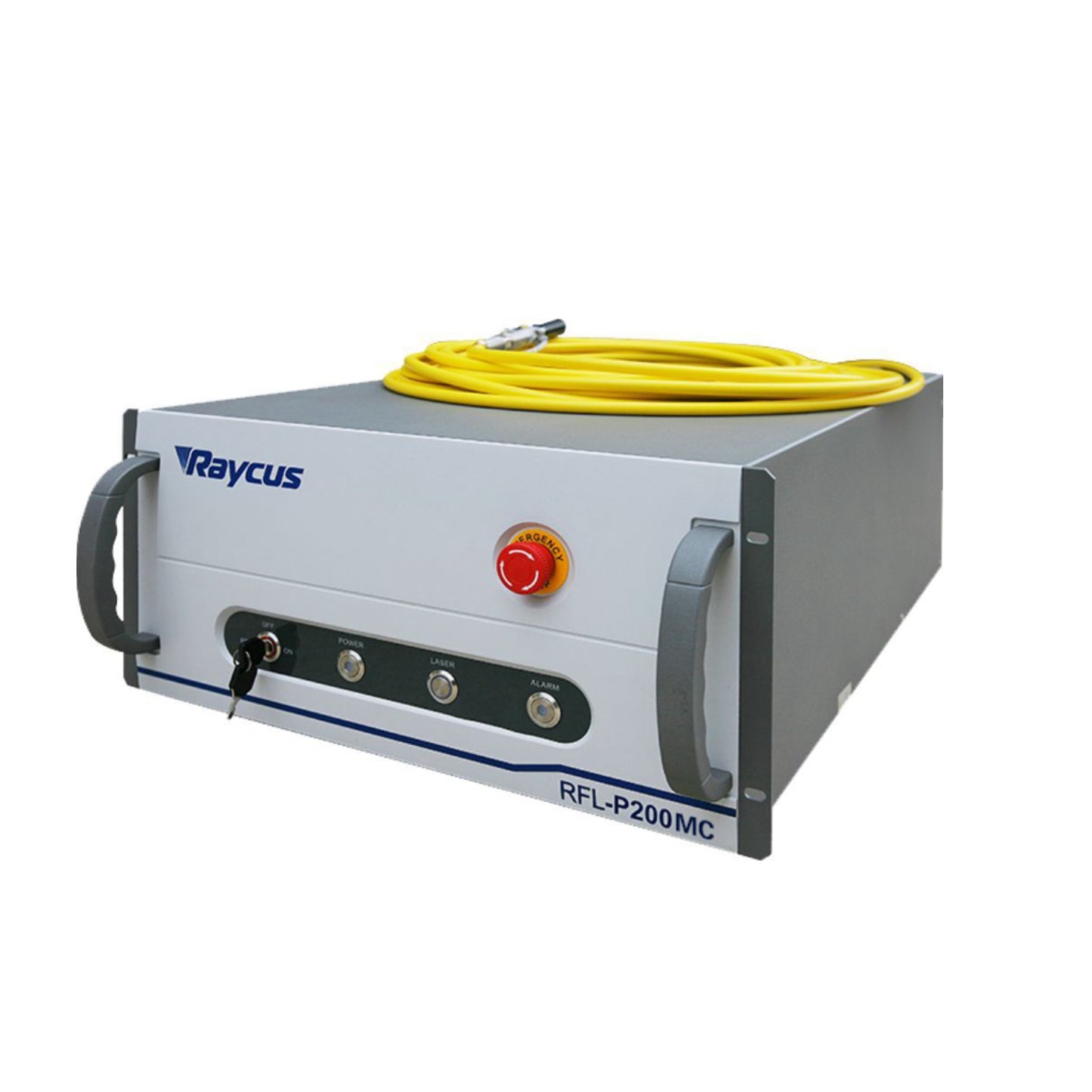
Laser: The laser is the core component of a laser cutting machine. Its function is to convert electrical energy into optical energy and produce a high-energy laser beam. Depending on its nature and power, the laser can be divided into various types, such as carbon dioxide lasers, fiber lasers, disk lasers, etc. Among them, fiber lasers have become the mainstream choice for current high-power laser cutting machines due to their high efficiency and reliability.
Power Supply: The power supply is the energy source of the laser. It converts electrical energy into high-energy electrical energy needed by the laser to make it emit light. The specifications and performance of the power supply vary depending on the type of laser. Generally, high-power laser cutting machines use high-frequency power supplies, which have the advantages of energy saving, high efficiency, and high reliability.
Cooling System: During operation, a laser generates a large amount of heat. If the heat cannot be effectively dissipated, it can affect the performance and service life of the laser. Therefore, the cooling system is an important component of the laser. It removes heat from the laser during operation through a series of cooling devices, such as water cooling jackets and heat dissipation fans.
Control System: The control system is mainly responsible for controlling the output power of the laser and regulating various parameters of the laser, such as current, voltage, frequency, etc., to make its output more stable and reliable. In addition, the control system also assumes the task of controlling cutting path and speed parameters.
The optical system of a high-power laser cutting machine focuses and adjusts the laser beam through components such as reflectors and lenses, which can increase the power density of the laser beam and achieve more accurate cutting results. At the same time, the design and adjustment of the optical system have a significant impact on the quality and efficiency of laser cutting, so the design and adjustment of the optical system are one of the keys to laser cutting.
Reflector: The reflector is an important component of the optical system. Its function is to reflect the laser beam, allowing it to pass through the cutting head and illuminate the surface of the metal material. The reflector is usually made of optical glass or quartz glass with high transparency and stability.
Lens: The lens is another important component of the optical system. Its function is to focus the laser beam into a smaller spot, increasing the power density of the laser beam. The lens is usually made of glass or quartz glass with a high refractive index, which can compress the laser beam to a very small size for more accurate cutting.
Focusing adjustment device: The focusing adjustment device is an important part of the optical system. Its function is to adjust the focusing position and size of the laser beam. The focusing adjustment device is usually adjusted by mechanical or electric means, capable of adjusting according to parameters such as the thickness of the metal material and cutting speed.
Collimating device: The collimating device ensures that the laser beam travels in a straight line, allowing the laser beam to illuminate the surface of the metal material accurately. The collimating device is usually adjusted by optical elements such as lenses or reflectors, capable of adjusting according to the shape and size of the metal material.
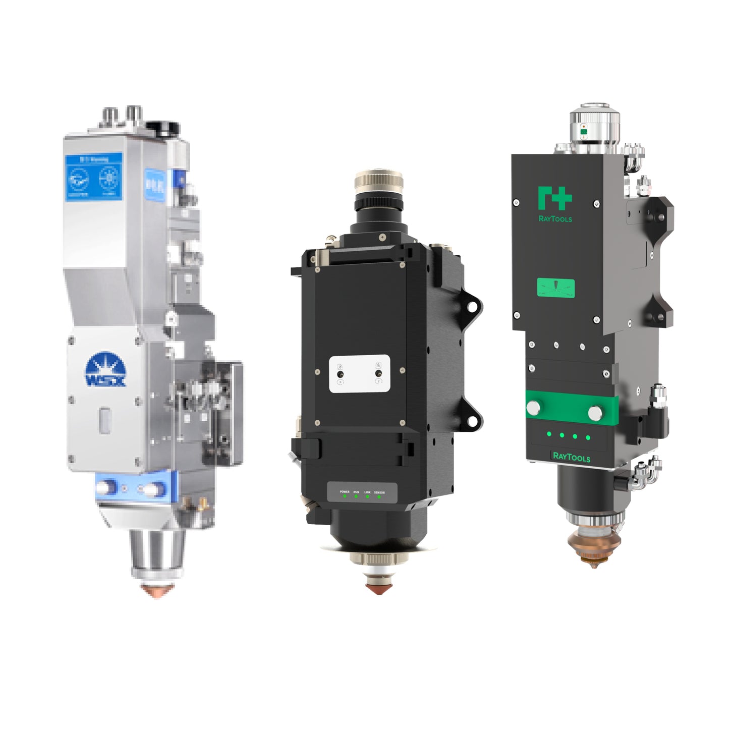
As an important component of a high-power laser cutting machine, the cutting head system mainly includes a nozzle, a focusing lens, and a focusing tracking detection system. Its working principle is to assist laser beam cutting of metal materials through the generation of airflow by the nozzle, focus the laser beam into a high-energy density spot by the focusing lens, andmonitor and adjust the position and height of the laser beam through the focusing tracking detection system to achieve high-quality and efficient metal cutting.
Nozzle: The nozzle is an important part of the cutting head system. Its function is to generate airflow to assist the laser beam in cutting metal materials. The nozzles come in different forms, including parallel, converging, and cone-shaped ones, and are generally made of stainless steel or copper. The concentricity of the nozzle has a significant impact on the cutting quality, so the nozzle is usually aligned with the laser cutting head to achieve a better cutting cross-section.
Focusing Lens: The focusing lens has the function of focusing the laser beam into a high-energy density spot, making it possible to cut metal materials. The lens is typically made of optical glass or quartz glass with high transparency and stability. Depending on the type of laser beam, there are different types of focusing lenses, generally divided into long-focus and short-focus ones, which are suitable for thick and thin plates, respectively.
Focusing Tracking Detection System: The focusing tracking detection system is one of the key technologies for laser cutting processing. In laser cutting, the laser focusing head must keep the focus constantly on the workpiece. Once the focus position shifts, it will affect the cutting quality of the product. The focusing tracking system is typically composed of a focusing cutting head and a tracking sensor system. Its function is to monitor the position of the focus point in real time through sensors and automatically adjust the position and height of the cutting head based on the monitoring results to ensure that the focus of the laser beam is always on the workpiece.
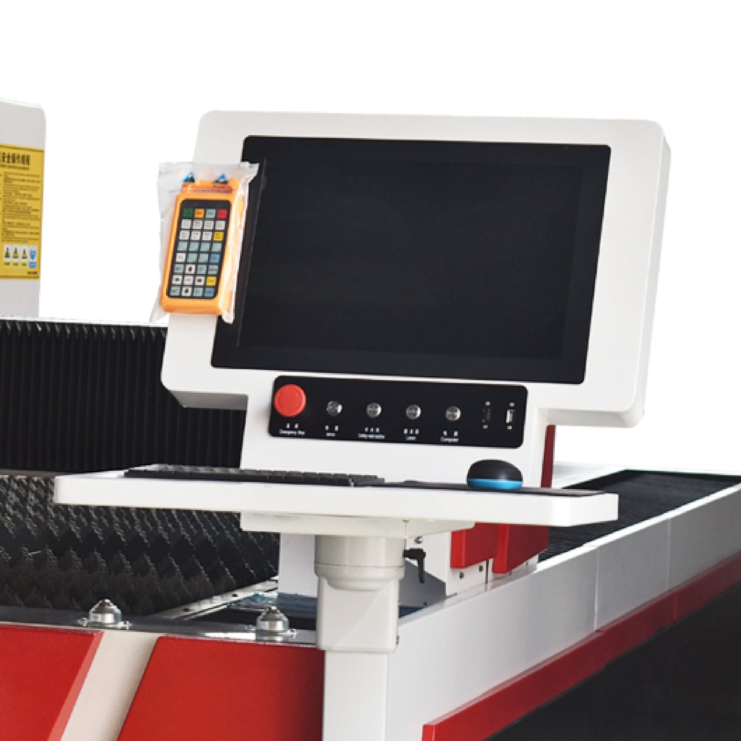
The numerical control system acts as the control center of the high-power laser cutting machine. It achieves precise control and adjustment of the laser beam through components such as the CNC unit, man-machine interface, input/output interface, and motion control unit, in order to achieve high-quality and efficient metal cutting.
CNC Unit: The CNC unit is the core of the numerical control system. It receives the processing path and technical parameters input by the user and calculates and controls the processing trajectory of the laser beam according to preset programs and algorithms. The CNC unit typically uses high-performance computer chips and professional motion control algorithms to achieve real-time monitoring and adjustment of the processing process, ensuring processing quality and efficiency.
Man-machine Interface: The man-machine interface acts as a bridge between the user and the numerical control system. It provides a friendly graphical interface that displays processing information and operation options, allowing the user to conveniently input and output operations. The man-machine interface typically includes components such as a control panel, display screen, and keyboard, where the user can input processing paths and technical parameters through the keyboard, and view processing status and results on the display screen or other external devices.
Input/Output Interface: The numerical control system communicates with external devices through the input/output interface. It can transmit the processing path and technical parameters input by the user to the CNC unit, and can also output the processing status and results to the display screen or other external devices. Additionally, the numerical control system can receive status signals from external devices through the input/output interface, to ensure stability and safety during processing.
Motion Control Unit: The motion control unit is responsible for controlling laser beam movement within the numerical control system. It controls the actions and speed of the laser based on the instructions output by the CNC unit, while monitoring the position and status of the laser beam to ensure precision and stability during processing. The motion control unit typically uses professional motion control algorithms and high-performance control hardware, possessing characteristics of high precision and efficiency.
The auxiliary system of a high-power laser cutting machine has an important impact on the stability and cutting efficiency of the entire equipment. It mainly includes a water cooling system, assist gas, and protective gas curtain.
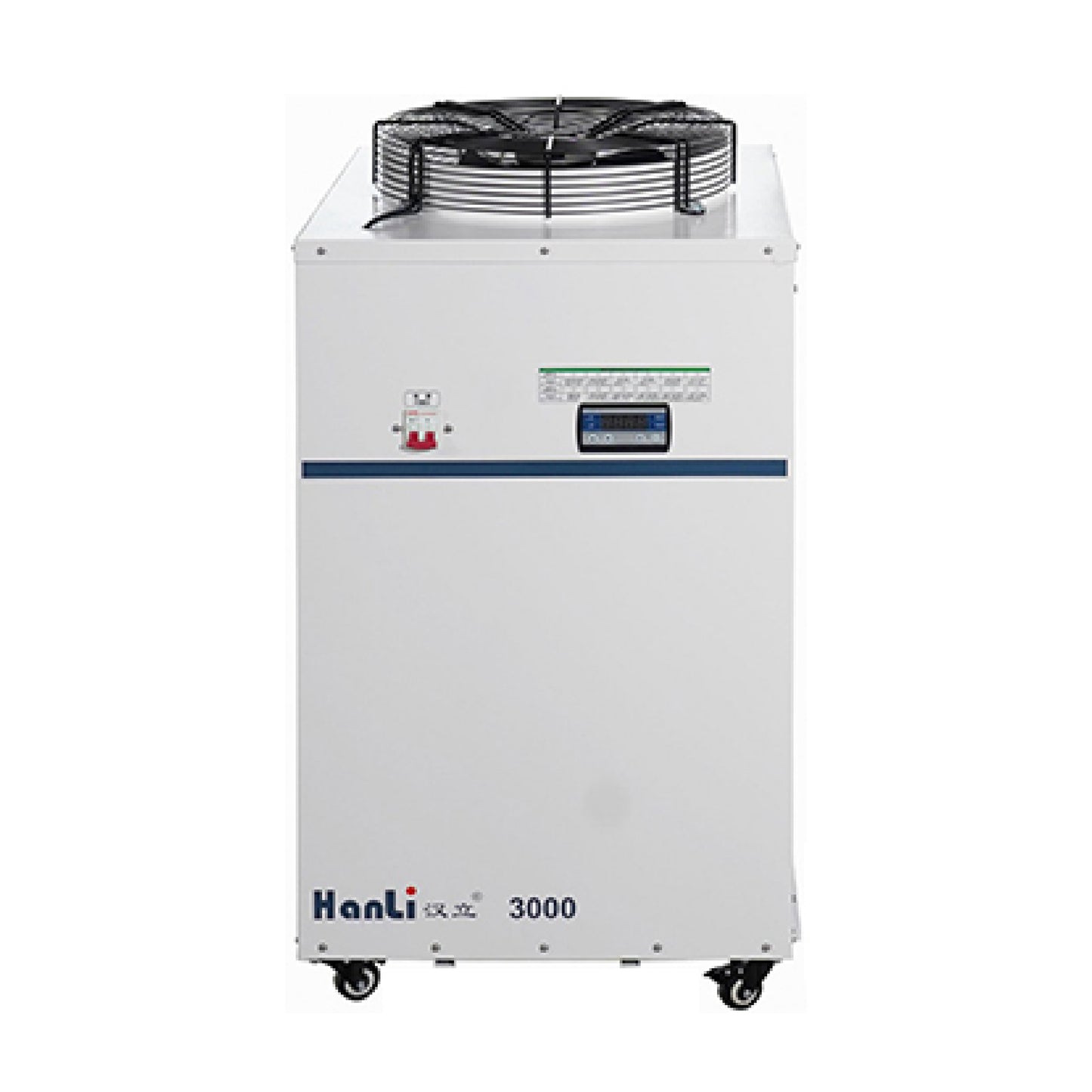
Water Cooling System: In high-power laser cutting machines, lasers need to work continuously and efficiently, so appropriate cooling is necessary. The water cooling system is designed to meet this demand by cooling the laser through dedicated cooling water channels, ensuring its normal operation. It is particularly important to note that the quality and flow rate of the cooling water have a significant impact on the cooling effect and the lifespan of the equipment, so regular maintenance and replacement are necessary.
Assist Gas: Assist gas plays an important role in laser cutting. During laser cutting, assist gas helps to blow away the cutting slag, protect the cutting head lens from pollution, and also help to improve cutting speed and quality. Generally speaking, different assist gases have different effects on different metal materials, so the appropriate assist gas should be selected according to the type of metal material and cutting requirements.
Protective Gas Curtain: The protective gas curtain mainly protects the laser cutting head. During laser cutting, the protective gas curtain can effectively prevent reactions between oxygen, nitrogen, and other assist gases with the metal material under high temperatures, thereby affecting the cutting quality. At the same time, the protective gas curtain can also prevent laser beam from overflowing, avoiding harm to operators.
The working process of the laser cutting machine is as follows:
Input Graphic: The graphic to be cut is input into the computer in the form of CAD or CAM software. This step can be achieved by manually drawing or importing existing CAD files. When inputting graphics, it is necessary to ensure the accuracy and precision of the graphics for the subsequent cutting process to proceed smoothly.
Computer-Aided Design (CAD/CAM): Using specific software on a computer to design, layout, and optimize the input graphics. This step needs to consider the size, shape, thickness of the material, as well as the shape and size of the required cutting. CAD/CAM software helps us edit, modify, and improve graphics to meet the needs and cutting requirements of different customers.
In CAD/CAM software, operations such as graphic drawing, modification, deletion, rotation, scaling can be performed, and graphic layout and optimization can also be carried out to ensure cutting efficiency and accuracy. In addition, CAD/CAM software can provide three-dimensional modeling functions that can better showcase product appearance and structure, helping clients better understand products.
After completing the CAD/CAM design, cutting path data can be output and transmitted to the numerical control laser cutting machine for cutting operations. Therefore, the precision and accuracy of CAD/CAM software will directly affect the cutting quality and accuracy. Therefore, when using CAD/CAM software for design, carefulness and precision are necessary to ensure good cutting results.
Optical path adjustment is a crucial step that involves adjusting the path and parameters of the laser beam according to the designed graphics to ensure that the laser beam can accurately illuminate the desired cutting position. The steps include:
Adjusting the laser power: Laser power is one of the important factors affecting the cutting effect. To ensure that the laser beam can accurately cut the material, the laser power needs to be adjusted according to the graphic design and material properties. The adjustment of laser power can be achieved by changing the current or voltage of the laser.
Adjusting the spot size and shape: The spot is the light spot on the surface of the material generated by the laser beam, and its size and shape also have an important impact on the cutting effect. To enable the laser beam to accurately illuminate the desired cutting position, the spot size and shape need to be adjusted. Typically, the spot size and shape can be adjusted through optical components such as lenses and mirrors.
Adjusting the focal length and focus position of the lens: The focal length and focus position of the lens have an important impact on the focusing effect of the laser beam and the cutting accuracy. To ensure that the laser beam can accurately focus on the desired cutting position, adjustments need to be made to the focal length and focus position. Typically, the focal length and focus position can be adjusted by rotating the adjustment ring on the lens.
During optical path adjustment, care and caution are required to ensure that each parameter adjustment is accurate. At the same time, necessary testing and verification need to be conducted to ensure that the laser beam can accurately illuminate the desired cutting position. Generally, optical path adjustment needs to be performed by professional technicians or experienced operators to ensure stable and accurate cutting results.
Trial cutting is an important step before formal cutting with a numerical control laser cutting machine. Its purpose is to check the accuracy and speed of the cutting to ensure that they meet the requirements. Trial cutting can reveal potential problems and areas for improvement, providing a reference and basis for the formal cutting process.
During the trial cutting process, a test piece is typically selected that is made of the same or similar material to the formal cutting material. This allows for a better evaluation of the cutting effectiveness and adaptability. During the trial cutting process, technical personnel can adjust parameters such as the cutting head position and height, laser power, and cutting speed to optimize the cutting effect.
The steps of trial cutting include the following:
Selecting a test piece: Select a test piece made of the same or similar material to the formal cutting material to conduct the test. This allows for a better evaluation of the cutting effectiveness and adaptability.
Adjusting parameters: Based on the material attributes of the test piece and the graphic design, adjust parameters such as the position and height of the cutting head, laser power, and cutting speed. These parameter adjustments can be made through the operating panel or CAD/CAM software.
Trial cutting process: Start the numerical control laser cutting machine and conduct trial cutting along preset paths. During the trial cutting process, observe the quality and effectiveness of the cutting, including the smoothness of the edges, the roughness of the cut surface, and the presence of any thermal impact areas.
Result evaluation: After the trial cutting is completed, evaluate the cutting effectiveness. Measure the size and shape of the test piece and compare it with the CAD design to evaluate the cutting accuracy and quality. Additionally, inspect the quality of the cutting edges, such as the presence of burrs or melt residue.
Parameter adjustment: Based on the results of the trial cutting, make adjustments to the parameters. If the accuracy and quality of the cutting do not meet the requirements, adjust parameters such as the optical path and other parameters to optimize the cutting effectiveness. For example, adjust the laser power, cutting speed, and position and height of the cutting head.
Repeat trial cutting: After adjusting the parameters, conduct another trial cutting to verify the adjustment results and feasibility. If the accuracy and quality of the cutting meet the requirements, proceed to the formal cutting stage.
Trial cutting is an iterative process that may require multiple trial cuts and parameter adjustments to achieve ideal cutting effectiveness. During this process, patience and professional guidance from technical personnel are required to ensure stable cutting quality and accuracy.
Formal cutting is the process of using a numerical control laser cutting machine to start the formal cutting process after trial cutting and parameter adjustment. During the formal cutting process, the numerical control system automatically controls the laser beam to move according to the pre-designed path, while tracking the movement of the material to ensure that the laser beam can accurately cut out the desired shape and size.
The process of formal cutting includes the following steps:
Preparation: Before starting the formal cutting process, it is necessary to check the cutting area to ensure that there are no obstacles or impurities. At the same time, the material needs to be placed in the correct position and the size and thickness of the material need to be confirmed to ensure that they meet the requirements.
Parameter Setting: Based on the results of the trial cutting and the material properties, set the parameters such as laser power, cutting speed, and so on. These parameter settings can be done through the operation panel or CAD/CAM software. In addition, the cutting path and program need to be set to ensure that the laser beam can move along the preset path.
Start Cutting: Start the numerical control laser cutting machine, and the laser beam automatically moves under the control of the numerical control system while tracking the movement of the material. During the cutting process, the laser beam irradiates the surface of the material, forming a molten and vaporized area to achieve cutting.
Real-time Monitoring: During the cutting process, the numerical control system monitors in real time the relative position between the laser beam and the material to ensure the accuracy and precision of the cutting. If any errors or problems are detected, the system will automatically adjust and correct them.
Cutting Completion: When the cutting is completed, the equipment will automatically stop running and give a prompt sound or signal. At this time, the operator can inspect and measure the cut parts to confirm whether the cutting quality and accuracy meet the requirements.
Formal cutting is a high-precision and high-efficiency process that requires ensuring that each parameter setting and adjustment is accurate and correct. At the same time, operators need to have rich experience and skills to handle unexpected situations and meet the requirements of different material attributes.
Cooling system is usually equipped with numerical control laser cutting machine to ensure that the laser can maintain stable performance during the cutting process. The cooling system is to effectively reduce the temperature of the laser, thereby avoiding cutting errors caused by temperature fluctuations.
Working principle of cooling system: Cooling system usually adopts water cooling or air cooling way to cool. Water-cooled cooling system uses circulating water to carry away the heat generated by the laser and release it to the outside through a radiator. Air-cooled cooling system uses a fan to blow cold air onto the laser and release the heat to the outside through a heat sink.
System composition: The cooling system usually consists of a radiator, a water pump or fan, a water tank or filter, and a temperature sensor.
Radiator and water pump or fan: The radiator and water pump or fan are the core components of the water-cooled cooling system. The water pump withdraws water from the water tank and flows through the laser, carrying away the heat generated by the laser. The radiator releases the heat to the outside and keeps the water temperature within a certain range. In an air-cooled cooling system, a fan is used to blow cold air onto the laser and release the heat through a heat sink.
Water tank and filter: In a water-cooled cooling system, the water tank is used to store circulating water, and the filter is used to filter impurities in the water to keep the water clean and prevent blockage of the radiator.
Temperature sensor: The temperature sensor is used to monitor the temperature of the laser, and feedback the temperature signal to the control system. The control system adjusts the power of the laser or the operating state of the cooling system according to the temperature signal, thereby maintaining the temperature stability of the laser.
The cooling system plays a crucial role in a numerical control laser cutting machine. It can effectively reduce the temperature of the laser, avoid cutting errors caused by temperature fluctuations, and thereby ensure the stability and accuracy of the cutting process.
To meet the needs of different customers, numerical control laser cutting machines typically have a variety of different cutting modes and functions, such as rotation cutting, sway cutting, multi-axis linkage, etc. These functions can be personalized and customized according to customer needs to meet various cutting requirements of different shapes and structures.
Rotation cutting is a common cutting mode that can create circular or elliptical cutting areas on the material. By controlling the rotation speed of the laser beam and the movement speed of the material, circular or elliptical cutting areas of different sizes and shapes can be formed on the material. This cutting mode is suitable for cutting circular or elliptical parts, such as gears, bearings, etc.
Sway cutting is also a common cutting mode. By controlling the angle and amplitude of the laser beam's oscillation on the material surface, different shapes can be cut. For example, by controlling the left-right oscillation angle and amplitude of the laser beam on the material surface, rectangular, trapezoidal, triangular, etc. different shapes can be cut. This cutting mode is suitable for parts that require cutting into different shapes, such as brackets, guides, etc.
Multi-axis linkage is an advanced cutting mode. By controlling the movement of the laser beam on multiple axes on the material surface, complex graphics and structures can be cut. For example, by controlling the movement of the laser beam on the X, Y, and Z axes, three-dimensional structures can be cut. This cutting mode is suitable for parts that require cutting into complex graphics and structures, such as automotive components, aerospace components, etc.
In terms of efficient production with automation production lines, numerical control laser cutting machines can be integrated with other equipment such as robots and conveyor belts to achieve automated and efficient cutting production. Through the cooperation of automation production lines, production efficiency can be greatly improved, labor costs can be reduced, and product quality and consistency can be guaranteed. For example, robots can automatically place materials in the cutting area, and conveyor belts can automatically transport cut parts to the next process, achieving continuous automated production and improving production efficiency and quality.
Share with