1
/
of
8
JTM Intelligent Equipment Co., Ltd.
HCGMT® Two Machines Linked Electro-Hydraulic Servo Press Brake Customizable
HCGMT® Two Machines Linked Electro-Hydraulic Servo Press Brake Customizable
| JTM Electro-hydraulic Synchronous Servo Bending Machine Technical Parameters | |||||||||||||||
| Model | Fuel Tank Capacity | Nominal Pressure | Bending Length | Fast Speed | Return Speed | X-axis Stroke | X-axis Speed | R-axis Stroke | R-axis Speed | Column Spacing | Throat Depth | Stroke | Opening Height | Main Motor Power | Size |
| L | KN | MM | MM/MIN | MM/MIN | MM | MM/S | MM | MM/S | MM | MM | MM | MM | KW | MM (L*W*H) | |
| 50T/1300 | 130 | 500 | 1300 | 13 | 160 | 500 | 350 | 200 | 200 | 1120 | 250 | 150 | 460 | 5.5 | 1800*1500*2300 |
| 50T/2000 | 130 | 500 | 2000 | 13 | 160 | 500 | 350 | 200 | 200 | 1600 | 250 | 150 | 460 | 5.5 | 2600*1500*2300 |
| 70T/1600 | 130 | 700 | 1600 | 13 | 160 | 500 | 350 | 200 | 200 | 1300 | 300 | 150 | 460 | 5.5 | 2300*1600*2500 |
| 70T/2500 | 170 | 700 | 2500 | 13 | 160 | 500 | 350 | 200 | 200 | 2050 | 300 | 150 | 460 | 5.5 | 3100*1600*2500 |
| 70T/3200 | 170 | 700 | 3200 | 13 | 160 | 500 | 350 | 200 | 200 | 2700 | 300 | 150 | 460 | 5.5 | 3700*1600*2500 |
| 80T/2500 | 170 | 800 | 2500 | 12 | 145 | 500 | 350 | 200 | 200 | 2050 | 300 | 150 | 460 | 7.5 | 3100*1600*2600 |
| 110T/2500 | 170 | 1100 | 2500 | 12 | 160 | 500 | 350 | 200 | 200 | 2050 | 400 | 200 | 480 | 11 | 3100*1800*2600 |
| 110T/3200 | 170 | 1100 | 3200 | 12 | 160 | 500 | 350 | 200 | 200 | 2700 | 400 | 200 | 480 | 11 | 3800*1800*2600 |
| 110T/4000 | 170 | 1100 | 4000 | 12 | 160 | 500 | 350 | 200 | 200 | 3100 | 400 | 200 | 480 | 11 | 4600*1800*2600 |
| 110T/4100 | 170 | 1100 | 4100 | 12 | 160 | 500 | 350 | 200 | 200 | 3600 | 400 | 200 | 480 | 11 | 4700*1800*2700 |
| 135T/3200 | 170 | 1350 | 3200 | 10 | 130 | 500 | 350 | 200 | 200 | 2700 | 400 | 200 | 480 | 11 | 3800*1800*2700 |
| 135T/4000 | 170 | 1350 | 4000 | 10 | 130 | 500 | 350 | 200 | 200 | 3100 | 400 | 200 | 480 | 11 | 4600*1800*2700 |
| 135T/4100 | 170 | 1350 | 4100 | 10 | 130 | 500 | 350 | 200 | 200 | 3600 | 400 | 200 | 480 | 11 | 4700*1800*2700 |
| 170T/2500 | 300 | 1700 | 2500 | 10 | 100 | 500 | 350 | 200 | 200 | 2050 | 450 | 200 | 480 | 15 | 3100*2000*2800 |
| 170T/3200 | 300 | 1700 | 3200 | 10 | 100 | 500 | 350 | 200 | 200 | 2700 | 450 | 200 | 480 | 15 | 3800*2000*2800 |
| 170T/4000 | 300 | 1700 | 4000 | 10 | 100 | 500 | 350 | 200 | 200 | 3100 | 450 | 200 | 480 | 15 | 4600*2000*2800 |
| 170T/4100 | 300 | 1700 | 4100 | 10 | 100 | 500 | 350 | 200 | 200 | 3600 | 450 | 200 | 480 | 15 | 4700*2000*2800 |
| 220T/2500 | 300 | 2200 | 2500 | 9 | 105 | 500 | 350 | 200 | 200 | 2050 | 450 | 200 | 480 | 18.5 | 3100*2200*2850 |
| 220T/3200 | 300 | 2200 | 3200 | 9 | 105 | 500 | 350 | 200 | 200 | 2600 | 450 | 200 | 480 | 18.5 | 3800*2200*2850 |
| 220T/4000 | 300 | 2200 | 4000 | 9 | 105 | 500 | 350 | 200 | 200 | 3100 | 450 | 200 | 480 | 18.5 | 4600*2200*2850 |
| 220T/5000 | 300 | 2200 | 5000 | 9 | 105 | 500 | 350 | 200 | 200 | 4000 | 450 | 200 | 480 | 18.5 | 4600*2200*2850 |
| 250T/2500 | 460 | 2500 | 2500 | 8.5 | 100 | 500 | 350 | 200 | 200 | 2000 | 450 | 250 | 540 | 22 | 3100*2000*2900 |
| 250T/3200 | 460 | 2500 | 3200 | 8.5 | 100 | 500 | 350 | 200 | 200 | 2600 | 450 | 250 | 540 | 22 | 3500*2000*2900 |
| 250T/4000 | 460 | 2500 | 4000 | 8.5 | 100 | 500 | 350 | 200 | 200 | 3100 | 450 | 250 | 540 | 22 | 4300*2100*3100 |
| 250T/5000 | 460 | 2500 | 5000 | 8.5 | 100 | 500 | 350 | 200 | 200 | 3800 | 450 | 250 | 540 | 22 | 5300*2150*3150 |
| 250T/6000 | 460 | 2500 | 6000 | 8.5 | 100 | 500 | 350 | 200 | 200 | 4800 | 450 | 250 | 540 | 22 | 6300*2150*3150 |
| 300T/3200 | 650 | 3000 | 3200 | 8.5 | 110 | 500 | 350 | 200 | 200 | 2600 | 500 | 250 | 570 | 22 | 3500*2250*3200 |
| 300T/4000 | 650 | 3000 | 4000 | 8.5 | 110 | 500 | 350 | 200 | 200 | 3100 | 500 | 250 | 570 | 22 | 4300*2500*3400 |
| 300T/5000 | 650 | 3000 | 5000 | 8.5 | 110 | 500 | 350 | 200 | 200 | 3800 | 500 | 250 | 570 | 22 | 5300*2500*3400 |
| 300T/6000 | 650 | 3000 | 6000 | 8.5 | 110 | 500 | 350 | 200 | 200 | 4800 | 500 | 250 | 570 | 22 | 6300*2500*3400 |
| 400T/3200 | 760 | 4000 | 3200 | 8 | 80 | 980 | 220 | 200 | 40 | 2400 | 500 | 300 | 610 | 30 | 3500*2700*3500 |
| 400T/4000 | 760 | 4000 | 4000 | 8 | 80 | 980 | 200 | 200 | 40 | 3100 | 500 | 300 | 610 | 30 | 4300*2700*3500 |
| 400T/5000 | 760 | 4000 | 5000 | 8 | 80 | 980 | 200 | 200 | 40 | 3800 | 500 | 300 | 610 | 30 | 5300*2700*3500 |
| 400T/6000 | 760 | 4000 | 6000 | 8 | 80 | 980 | 200 | 200 | 40 | 4800 | 500 | 300 | 610 | 30 | 6300*2700*3500 |
| 400T/8000 | 760 | 4000 | 6000 | 8 | 80 | 980 | 200 | 200 | 40 | 6400 | 500 | 300 | 610 | 30 | 6300*2700*3500 |
| 500T/4000 | 760 | 5000 | 4000 | 8.5 | 90 | 980 | 220 | 200 | 40 | 3100 | 500 | 300 | 610 | 37 | 4300*2700*3500 |
| 500T/5000 | 760 | 5000 | 5000 | 8.5 | 90 | 980 | 200 | 200 | 40 | 3800 | 500 | 300 | 610 | 37 | 5300*2700*3500 |
| 500T/6000 | 760 | 5000 | 6000 | 8.5 | 90 | 980 | 200 | 200 | 40 | 4800 | 500 | 300 | 610 | 37 | 6300*2700*3600 |
| 600T/3200 | 1050 | 6000 | 3200 | 8.5 | 85 | 980 | 200 | 200 | 40 | 2300 | 600 | 320 | 650 | 45 | 4300*3300*3900 |
| 600T/4000 | 1050 | 6000 | 4000 | 8.5 | 85 | 980 | 200 | 200 | 40 | 3100 | 600 | 320 | 650 | 45 | 4300*3300*3900 |
| 600T/5000 | 1050 | 6000 | 5000 | 8.5 | 85 | 980 | 220 | 200 | 40 | 3800 | 600 | 320 | 650 | 45 | 5300*3300*3900 |
| 600T/6000 | 1050 | 6000 | 6000 | 8.5 | 85 | 980 | 200 | 200 | 40 | 4800 | 600 | 320 | 650 | 45 | 6300*3300*3900 |
| 600T/7000 | 1050 | 6000 | 7000 | 8.5 | 85 | 980 | 200 | 200 | 40 | 5600 | 600 | 320 | 650 | 45 | 7300*3300*3900 |
| 700T/6000 | 1050 | 7000 | 6000 | 8.5 | 85 | 980 | 200 | 200 | 40 | 4900 | 600 | 320 | 700 | 55 | 6300*3500*4000 |
| 800T/6000 | 1800 | 8000 | 6000 | 8 | 90 | 980 | 220 | 200 | 40 | 4600 | 600 | 320 | 800 | 30*2 | 6300*3500*4000 |
| 800T/7000 | 1800 | 8000 | 7000 | 8 | 90 | 980 | 200 | 200 | 40 | 5600 | 600 | 320 | 800 | 30*2 | 7300*3500*4200 |
| 800T/8000 | 1800 | 8000 | 8000 | 8 | 90 | 980 | 200 | 200 | 40 | 6600 | 600 | 320 | 800 | 30*2 | 8300*3600*4500 |
| 800T/10000 | 1800 | 8000 | 10000 | 8 | 90 | 980 | 200 | 200 | 40 | 7800 | 600 | 320 | 800 | 30*2 | 10300*3600*4900 |
| Note: All parameters are dynamic and for reference only. For more information, please contact customer service. | |||||||||||||||
There are two optical grating displays on each side of the machine, which constantly check the position of the slider and feedback the information to the control system. Then, the control system controls the electro-hydraulic valve to drive two cylinders to move simultaneously. As the optical grating display is installed on the "C" board instead of directly on the column, the deviation of the slider and the fuselage will not affect the measurement and control accuracy when working. When both machines work simultaneously, the potentiometer installed in each machine transforms the mechanical synchronous signal into the same electronic signal and feedbacks it to the synchronous board and control system. After being amplified by the Bose amplifier, the signal is controlled by the electro-hydraulic synchronous valve to achieve high accuracy.
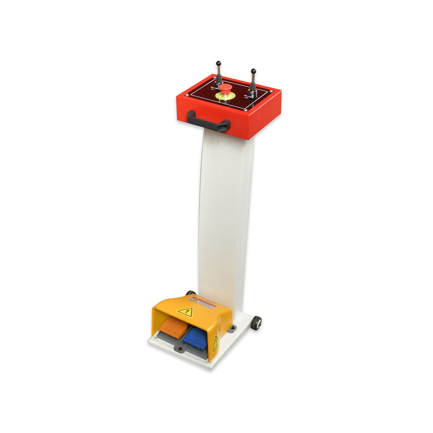
Hydraulic System Including:
Hydraulic Pump: This is the core component of the hydraulic system, which is driven by an electric motor to draw hydraulic oil from the tank and pump it under pressure into the hydraulic circuit.
Control Valve: These valves control the direction, flow rate, pressure, and speed of the hydraulic oil. They are usually actuated by electrical or mechanical signals and regulate the movement and stopping of the slider.
Hydraulic Pipe: Hydraulic pipes connect various components together to form an enclosed system. Hydraulic oil flows through the pipes and transmits pressure to the actuating elements.
Hydraulic Filter: This critical component filters impurities from the hydraulic oil to maintain cleanliness and ensure normal operation of the hydraulic system. If the hydraulic oil is contaminated, it may cause system blockage or damage.
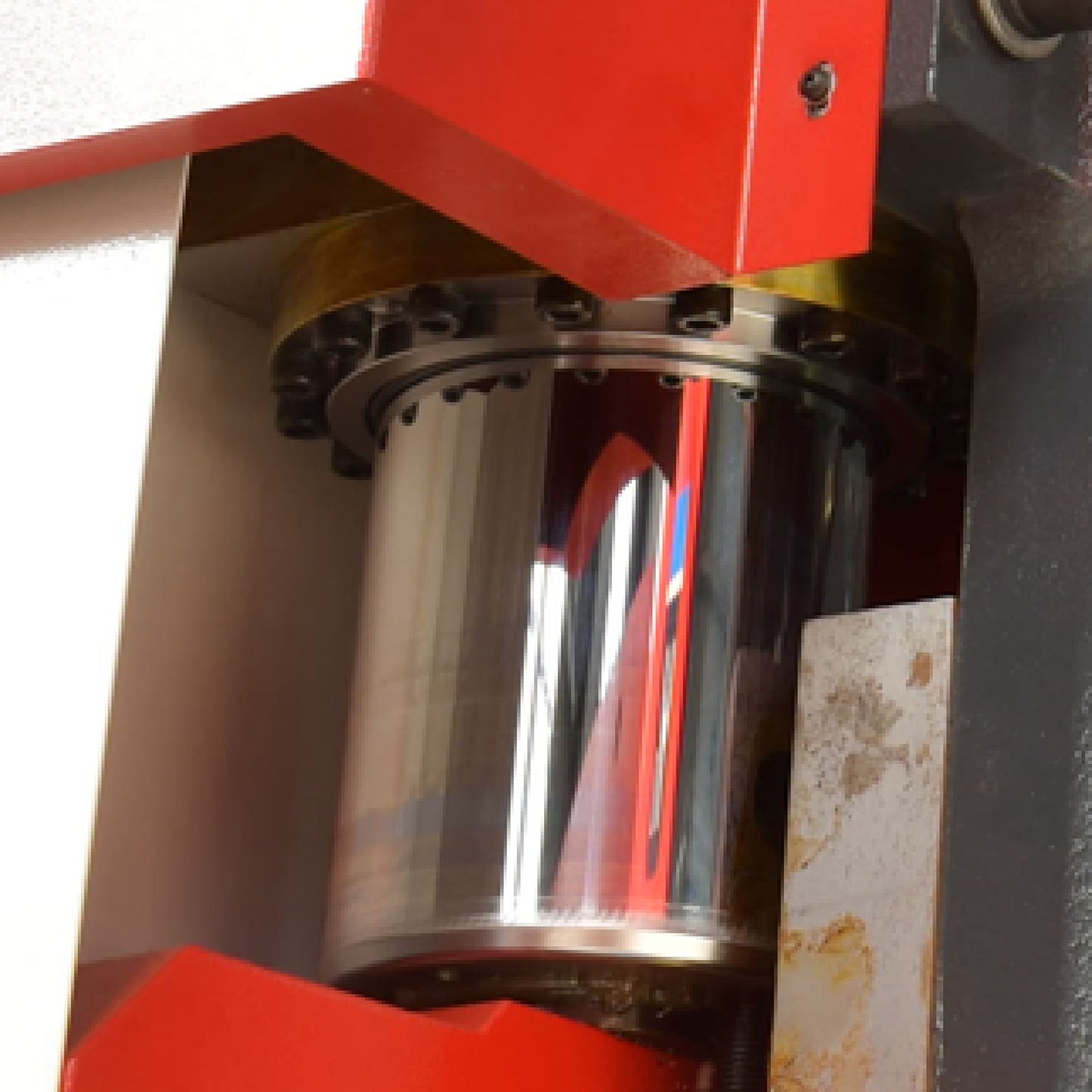
Actuating Element: These include cylinders, motors, etc., which convert hydraulic energy into mechanical energy and push the slider to perform linear reciprocating motion.
Pressure Sensor: This sensor detects the pressure in the hydraulic system and feeds back the pressure signal to the control system, which adjusts the pump's operation or the control valve's opening based on actual needs to maintain stable system pressure.
Cooling System: During operation, the hydraulic system generates heat that needs to be dissipated by a cooling system to prevent excessive heat from damaging the hydraulic oil and components.
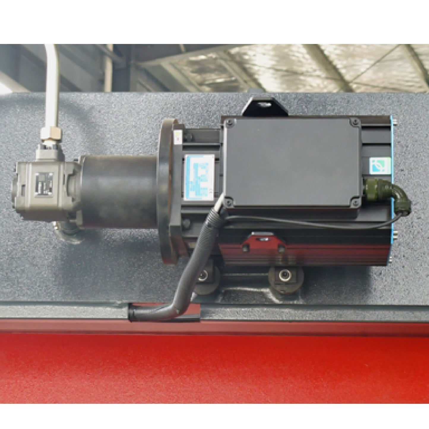
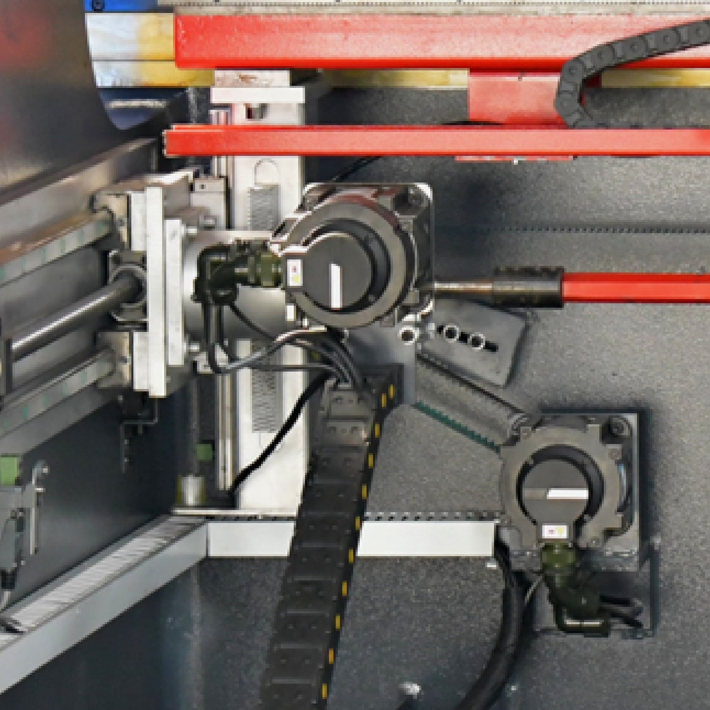
The servo motor in the dual-machine linked electro-hydraulic synchronous servo NC bending machine is one of the important components of the equipment, whose main function is to convert electrical energy into mechanical energy to drive the slider to perform linear reciprocating motion, thereby realizing the bending processing of the plate material.
The servo motor has the following characteristics:
High control accuracy: Through advanced numerical control system control, accurate speed and position control can be achieved, ensuring the stability and accuracy of the slider's movement during bending, thereby effectively improving the accuracy and quality of bending processing.
Fast response: The servo motor has a fast response characteristic and can reach the set speed in a short time, achieving fast and slow speed switching to improve production efficiency.
Mechanical transmission system: The servo motor is connected to the slider through a mechanical transmission system, converting the rotating motion of the motor into the linear reciprocating motion of the slider. This system usually includes gears, crankshaft linkages, etc. to achieve precise transmission and motion control.
Good stability: The servo motor has good stability and reliability, can operate stably for a long time, and ensure the accuracy and quality of bending processing.
Easy to operate: Professional advanced numerical control system control, equipped with deflection compensation devices, operation is very simple and convenient, with low experience requirements for operators, simply by inputting correct step dimensions, it can perform bending processing.
The numerical control system in the dual-machine linked electro-hydraulic synchronous servo NC bending machine is the core of the entire equipment, which implements precise control over the entire bending processing process through specific algorithms and logic.
Machine Performance: The numerical control system determines the performance of the machine tool, including optimized design of stiffness and stability, application of finite element analysis, etc. These measures are to minimize the impact of bending deformation on workpiece quality and ensure the processing accuracy of the workpiece.
Real-time Feedback: The optical (magnetic) grating installed on the slider and the cylinder body can provide real-time feedback on the synchronization status between the two sides of the slider. When there is an error, the numerical control system will adjust through a proportional valve to promote synchronization between the two sides of the slider.
Closed-loop Control: The numerical control system, hydraulic control valve group, and optical grating together constitute a feedback closed-loop control system for the electro-hydraulic synchronous bending machine. The optical grating is responsible for real-time feedback, the numerical control system analyzes and adjusts the synchronization status between the two sides of the slider, and the hydraulic control valve group executes the adjustment command.
Precision and Speed: The dual-machine linked electro-hydraulic synchronous servo NC bending machine is designed and functionally optimized to ensure high-precision and high-efficiency sheet metal processing equipment.
The mechanical transmission system in the dual-machine linked electro-hydraulic synchronous servo NC bending machine mainly consists of transmission shaft, gears, and crankshaft linkage components, etc., whose function is to convert the rotating motion of the servo motor into linear reciprocating motion of the slider, thereby realizing the bending processing of the plate material.
Transmission Shaft: The transmission shaft is an important component of the mechanical transmission system, which connects the motor and gear, and transfers the rotating motion of the motor to the gear. The precision and stability of the transmission shaft have an important impact on the entire mechanical transmission system, so it needs to undergo precision processing and dynamic balance testing to ensure its quality and performance.
Gear: The gear is one of the most important components in the mechanical transmission system. Its quality and precision directly affect the performance and service life of the entire system. The gear changes the speed and direction of rotation of the transmission shaft, obtaining linear reciprocating motion of the slider. According to different bending requirements, different types of gears can be selected, such as spur gears and helical gears.
Crankshaft Linkage: The crankshaft linkage mechanism is the core part of the mechanical transmission system, which consists of crankshafts, connecting rods, and sliders, etc. The crankshafts are connected to the gears to receive the output rotation from the gears, and convert it into linear reciprocating motion of the slider through the connecting rods. Parameters such as length, angle, and position of the crankshaft linkage mechanism need to be accurately calculated and adjusted according to different bending requirements to ensure the accuracy and quality of bending processing.
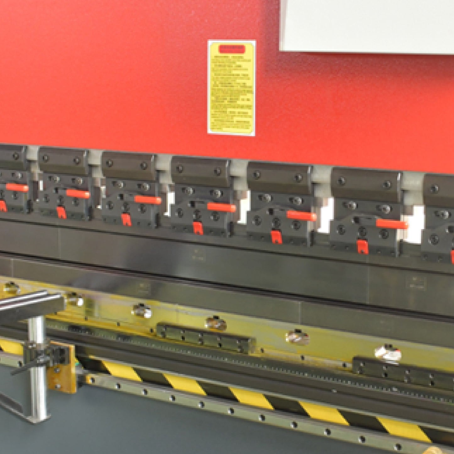
The slider and die are important components in the dual-machine linked electro-hydraulic synchronous servo NC bending machine, which are used to achieve bending processing of the plate material.
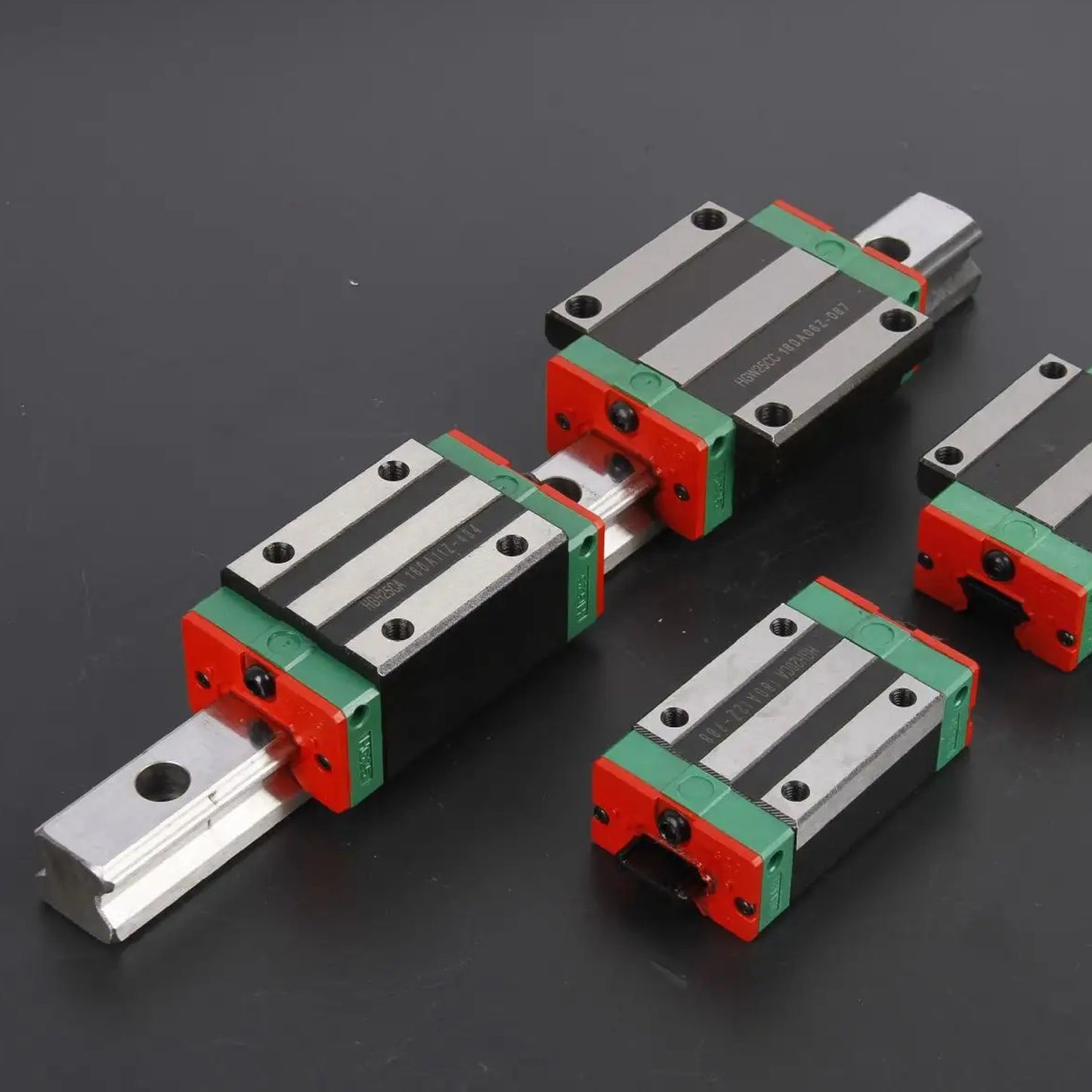
Slider: The slider is an important component of the dual-machine linked electro-hydraulic synchronous servo NC bending machine, which contacts the plate material and is driven by the oil cylinder embedded inside the slider to enable the slider to perform vertical reciprocating motion along the guide rail. The stroke length and speed of the slider can be adjusted according to different bending requirements, and precise control of the numerical control system can achieve high-precision bending.
Die: The die is a mold used for bending processing in the dual-machine linked electro-hydraulic synchronous servo NC bending machine. It contacts the slider and bends the plate material into the desired shape. The design and manufacturing accuracy of the die directly affect the quality and accuracy of bending processing. Different shapes and sizes of dies can be selected according to different bending requirements, such as V-shaped dies and U-shaped dies.
The cooperation of the slider and die in the dual-machine linked electro-hydraulic synchronous servo NC bending machine can achieve high-precision and high-efficiency bending processing. Through precise control of the numerical control system, the motion trajectory of the slider and die can achieve precise matching, thereby ensuring the quality and accuracy of bending processing. In addition, the manufacturing materials and surface treatment of the slider and die also need to be selected and optimized according to specific application scenarios to improve service life and processing efficiency.
Share with